
The basic working of closed loop SEPIC is
same as the open loop SEPIC except the addition of the feedback loop. The
feedback circuit enables automation of the circuit as it changes the duty cycle
dynamically as the input is varied.
Feedback Loop: The output is given as
input to the arithmetic comparator. The other input to the comparator is the
required constant voltage. Here the error voltage is obtained which is fed as
input to the PI controller. The PI controller has two parameters ‘proportional
gain (Kp)’ and ‘integral gain (Ki)’. The values used are Kp = 0.045 and Ki =
0.91 which are based on Ziegler-Nichols method. The output of PI controller is
the control voltage. This voltage is given to the Saturation block which
ensures that the voltage level is within the amplitude of the sawtooth
repeating sequence. The output of the Saturation block is fed to the gain block
with gain value of 1.01. The Repeating sequence produces sawtooth wave of
frequency 100KHz which is used to produce pulses. The output from the gain is
compared with the sawtooth wave and based on the relational operator function a
pulse is generated which is given as the input to the GATE terminal of the
MOSFET. This circuit dynamically changes the duty cycle of SEPIC by varying the
ON and OFF time of the MOSFET.
SIMULATION
RESULTS:

Figure 8: Output of closed loop SEPIC for an input of 2V
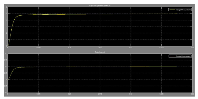
Figure 9: Output of closed loop SEPIC for an input of 5V


Figure 11: Output ripple current for an input of 10V
From the graph it is observed that ripple
current in open loop SEPIC is higher than that in closed loop SEPIC.
Average efficiency of open loop SEPIC is
observed to be at around 93%
Average efficiency of closed loop SEPIC is
observed to be at around 99%
The following table is tabulated for
closed loop SEPIC:
Input
Voltage(in V)
|
Loop
Response Time(in ms)
|
2
|
4
|
5
|
2
|
12
|
4.5
|
CONCLUSION:
As the result suggests, the open loop
SEPIC has more ripple current and voltage than that is desired in high level
applications. It is also not automatic as the duty cycle must be reset each
time the input is varied to get the desired output. Hence the need to design an
automatic SEPIC arises. The automation is brought about by the feedback loop.
The main controlling component of the feedback loop is the PI Controller which
also helps to reduce the steady state error voltage. With the use of PI
Controller the SEPIC becomes more robust and gives good dynamic response.
SEPIC can also be designed to act as a
multiple output isolated DC-DC converter. The main change is that the input to
the SEPIC is given through a transformer with 1:1 turns ratio. The secondary
coil is wound around the same core for all the multiple outputs. However it
becomes a bulky circuit as a different circuit has to be designed for each of
the multiple outputs as a different constant has to be set in the feedback network.
No comments:
Post a Comment