Tuesday 28 February 2017

DC DC SEPIC POWER CONVERTER: BASIC DESIGN AND ITS WORKING


INTRODUCTION:

They are many DC-DC conversion techniques available. The most basic technique is linear regulation. However the efficiency of this technique is very low. Hence switching regulation is used when higher efficiency is required. The design and working of switching regulators is complex as they contain non-linear components. Buck-Boost converter performs same operation as SEPIC but its efficiency is lower when compared to SEPIC. Hence SEPIC is preferred in high efficiency applications such as spacecrafts where power losses are critical.

SEPIC gives a constant output when the inputs are lower or higher or in the range of the constant output. The SEPIC operates at high efficiency in the range of 90%-95%. Open loop SEPIC has a lower efficiency when compared to the closed loop SEPIC. However due to some limitations the open loop SEPIC is not widely used in practical applications.It is best to use the SEPIC converter with feedback to hold a single output without the need for control when using a SEPIC as part of a large circuit.  

WORKING:

SEPIC configuration provides both buck and boost action in a single device depending on duty cycle. If the duty is higher than 50%, then it acts as a boost converter. If the duty cycle is less than 50%, then it works as a buck converter. If the duty cycle is exactly 50%, then output is same as the input.
Equations:
Duty cycle, D=Vo+Vd/Vin+Vo+Vd


Output voltage, D*Vin/(1-D)   
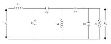
 Open loop SEPIC:
   
                                                    Figure 1: Basic SEPIC circuit diagram


This is the circuit diagram of the basic SEPIC topology. There are two stages of working i.e. when the MOSFET switch S1 is closed and when it is open.

When the MOSFET switch is closed:

                                          Figure 2: Open loop SEPIC when the switch is closed

When the switch S1 is closed, energy is stored in the input inductor L1 and the current through it increases. The voltage drop across this inductor is equal to the input voltage as the diode D1 is in open position during this mode. Inductor L2 is charged by capacitor C1. Capacitor C2 discharges through the load, thus giving an output. The equations in this mode of operation:


When the MOSFET switch is open:

                                         Figure 3: Open loop SEPIC when the switch is open

When switch S1 is open, the diode D1 comes in to play. As the diode D1 conducts, the input inductor current decreases, charging capacitor C1. The current through the second inductor L2, decreases linearly to charge the capacitor C2. The equations in this mode of operation:


MATLAB SIMULINK Circuit:
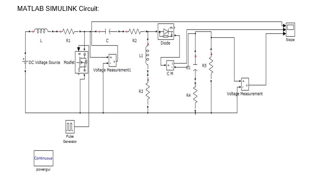

                                Figure 4: MATLAB SIMULINK open loop SEPIC circuit diagram

Circuit components:

Component Name
Value
L1
150 microH
L2
150 microH
C1
100 microF
C2
100 microF

The resistances R1, R2, R3 and R4 are parasitic resistances in the order of milli ohms.
The input and load resistance can be varied as the circuit follows line and load regulation respectively.

Drawbacks: In open loop SEPIC, there is some ripple current and voltage at the output which is undesirable. Also, the average efficiency is low when compared to closed loop SEPIC. However, the main drawback is that the duty cycle should be varied manually which is not suitable for most of the practical applications.


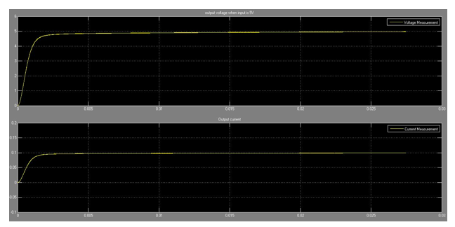
Figure 5: shows output voltage and current when input is 10V 


Figure 6: shows spike in the output volatge and current


Figure 7: shows ripple in ouput voltage and current


Saturday 25 February 2017

CLOSED LOOP APPROACH OF DC DC SEPIC POWER CONVERTER

CLOSED LOOP SEPIC:


                           Figure 5: MATLAB SIMULINK closed loop circuit diagram

The basic working of closed loop SEPIC is same as the open loop SEPIC except the addition of the feedback loop. The feedback circuit enables automation of the circuit as it changes the duty cycle dynamically as the input is varied.
Feedback Loop: The output is given as input to the arithmetic comparator. The other input to the comparator is the required constant voltage. Here the error voltage is obtained which is fed as input to the PI controller. The PI controller has two parameters ‘proportional gain (Kp)’ and ‘integral gain (Ki)’. The values used are Kp = 0.045 and Ki = 0.91 which are based on Ziegler-Nichols method. The output of PI controller is the control voltage. This voltage is given to the Saturation block which ensures that the voltage level is within the amplitude of the sawtooth repeating sequence. The output of the Saturation block is fed to the gain block with gain value of 1.01. The Repeating sequence produces sawtooth wave of frequency 100KHz which is used to produce pulses. The output from the gain is compared with the sawtooth wave and based on the relational operator function a pulse is generated which is given as the input to the GATE terminal of the MOSFET. This circuit dynamically changes the duty cycle of SEPIC by varying the ON and OFF time of the MOSFET.

SIMULATION RESULTS:


Figure 8: Output of closed loop SEPIC for an input of 2V


                           Figure 9: Output of closed loop SEPIC for an input of 5V  


                             Figure 10: Output of closed loop SEPIC for an input of 12V 


Figure 11: Output ripple current for an input of 10V

  
From the graph it is observed that ripple current in open loop SEPIC is higher than that in closed loop SEPIC.

Average efficiency of open loop SEPIC is observed to be at around 93%

Average efficiency of closed loop SEPIC is observed to be at around 99%

The following table is tabulated for closed loop SEPIC:

Input Voltage(in V)
Loop Response Time(in ms)
2
4
5
2
12
4.5

CONCLUSION: As the result suggests, the open loop SEPIC has more ripple current and voltage than that is desired in high level applications. It is also not automatic as the duty cycle must be reset each time the input is varied to get the desired output. Hence the need to design an automatic SEPIC arises. The automation is brought about by the feedback loop. The main controlling component of the feedback loop is the PI Controller which also helps to reduce the steady state error voltage. With the use of PI Controller the SEPIC becomes more robust and gives good dynamic response.

SEPIC can also be designed to act as a multiple output isolated DC-DC converter. The main change is that the input to the SEPIC is given through a transformer with 1:1 turns ratio. The secondary coil is wound around the same core for all the multiple outputs. However it becomes a bulky circuit as a different circuit has to be designed for each of the multiple outputs as a different constant has to be set in the feedback network.